
Beginner guide
By the end of this page you will have picked a board, run a project on the simulated bench, read what it prints in the serial monitor, made your own version of it in the circuit designer and exported a build sheet for the real thing. You need no parts and no board.
What you need
- Circuit Lab open in your browser or installed on your computer. See Install.
- About fifteen minutes.
A wide window shows the most at once. On a narrow screen the same parts are reached through tabs, as each step says.
A few words first
- A board is a small computer that runs one program and switches its pins on and off. Arduino, ESP32 and Raspberry Pi Pico boards are the common ones.
- A sketch is an Arduino program.
setup()runs once when the board starts, thenloop()runs again and again. - A pin is one leg of the board's header. Parts such as LEDs and buttons are wired to pins.
- The serial monitor shows text the board sends back over its USB cable. Sketches use
Serial.println()to report what they are doing.
1. Pick your board
The app opens on the Labs tab.
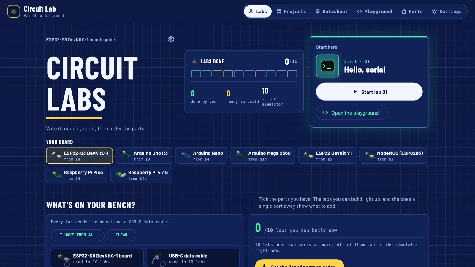
- 1Tabs — Labs, Projects, Datasheet, Playground, Parts and Settings.
- 2Labs done — How many labs of the course you have finished.
- 3Start lab 01 — Opens the first lab, or the next one you have not finished.
- 4Open the playground — Common parts already wired to your board, for any sketch.
- 5Your board — The course, the projects and the playground all follow this choice.
- 6What’s on your bench? — Tick the parts you own to see which labs you can build.
Under Your board, select the board you have or want to learn on. If you are not sure, keep the ESP32-S3 DevKitC-1, which is selected at first.
The whole page follows your choice: the course, the parts list and the board tour. The app remembers it next time.
Do not pick Raspberry Pi 4 / 5 for this guide. It is a Linux computer, so the app designs circuits for it but does not run them.
2. Open a project
Open the Projects tab.
Scroll to Ready-made for the and your board's name, and select the Input category.
Select Button toggle. Each press of a button flips an LED.
The project opens in the workspace. It shows:
- the pin map: every pin on the board, with the LED and the button tagged on the pins they use;
- the guide: what the project does, the parts for the real build, a wiring table and steps;
- the code editor, holding the project's sketch;
- the bench: a breadboard preview with the parts, and the serial monitor below it.
On a wide screen these sit side by side. On a narrow one they are the Guide, Code and Bench tabs.
3. Run it on the bench
Select Run at the top right, or press Ctrl + Enter or F5.
The bench shows running. On a narrow screen the app switches to the Bench tab by itself.
Find the button on the breadboard preview. The text under it says tap and hold.
Press and hold the button, then let go. While you hold it, it shows pressed · LOW. The LED next to it lights up and stays on.
Press the button again. The LED goes off.
Select Stop.
The sketch reads the button with digitalRead() and switches the LED with digitalWrite(), exactly as a real board would.
4. Read the serial monitor
Below the breadboard is the serial monitor. Each press printed a line, with the time since the sketch started, for example:
00:02.415 > on
00:04.031 > off
Now see how the simulator warns about a mistake that a real board would make silently.
In the code editor, find the line
pinMode(buttonPin, INPUT_PULLUP);and changeINPUT_PULLUPtoINPUT.The editor's header changes to edited · saved. Your changes are kept on this device.
Select Run.
A line starting with
[sim]appears in the serial monitor, in a different colour. It says the button's pin is floating, so it reads at random, and to useINPUT_PULLUP. The LED may flip on its own.Select Stop, and change
INPUTback toINPUT_PULLUP.Except on a phone-sized screen, you can also select Restore starter code (the round arrow at the top) and confirm with Restore.
INPUT_PULLUP holds the pin high until the button connects it to ground. Without it the pin is connected to nothing and picks up noise. Lines that start with [sim] are hints from the simulator, not output from your sketch.
TIP
The box under the monitor, type a command, press Enter, sends a line to the sketch. Try it with the Serial echo project in Basics: run it, type hello and press Enter.
5. Make it your own
You can edit a library project's code, but not its circuit. To change the circuit, make your own copy.
Back in Button toggle, select Customize at the top. On a phone-sized screen it is the icon with the sliders.
A copy called Button toggle (mine) opens with the circuit designer. On a narrow screen it is the Circuit tab.
Select Add part and choose LED.
A second LED, LED 2, appears in the list with a free pin chosen for it, and is tagged on the pin map. The coloured dots next to it set its colour.
Select Generate starter code for this circuit, then Replace.
The app writes a new sketch that sets up every part and exercises it.
Select Run.
The two LEDs light one after the other, and every half second the serial monitor prints the button's state,
button=up. Hold the button on the bench and it printsbutton=pressed.
Your copy is saved on this device. It is listed under Your projects on the Projects tab.
6. Export it
Select the Export button at the top right (the share icon).
Choose Build sheet (.md).
In a desktop app a save dialog opens. In a browser the file goes to your downloads, as
button-toggle-mine-build-sheet.md.
The build sheet is a Markdown file with the board, a wiring table, the parts with rough prices, the code, and how to upload it with the Arduino IDE. The same menu exports the program, a circuit diagram, the parts to order and a project file. See Export and import.
What you learned
- Your board on the Labs tab decides which board every project is wired for.
- Run starts the sketch on the bench, where you work the parts yourself.
- The serial monitor shows what the sketch prints, and
[sim]lines are the simulator's hints. - Customize makes an editable copy; Add part and Generate starter code for this circuit build on it.
- The Export menu turns a project into files for the real build.