
Boards and the datasheet
Circuit Lab knows eight boards. Each has its own header layout, its own rules in the simulator, a 3D model and a datasheet in plain words. This page lists them, then explains the board tour and the Datasheet tab.
The eight boards
| Board | Logic | Analog inputs | Good to know |
|---|---|---|---|
| ESP32-S3 DevKitC-1 | 3.3 V | 20, 12-bit | The default board, with its own course. Built-in RGB LED. |
| Arduino Uno R3 | 5 V | 6 (A0 to A5), 10-bit | PWM only on pins 3, 5, 6, 9, 10 and 11, the ~ pins |
| Arduino Nano | 5 V | 8 (A0 to A7), 10-bit | A6 and A7 are inputs only |
| Arduino Mega 2560 | 5 V | 16 (A0 to A15), 10-bit | PWM on pins 2 to 13 and 44 to 46 |
| ESP32 DevKit V1 | 3.3 V | 16, 12-bit | GPIO 34 to 39 are inputs only |
| NodeMCU (ESP8266) | 3.3 V | 1 (A0), 10-bit | Pins named D0 to D8. The built-in LED lights on LOW. |
| Raspberry Pi Pico | 3.3 V | 3 (GP26 to GP28), 12-bit | PWM on every pin |
| Raspberry Pi 4 / 5 | 3.3 V | None | Not simulated. Design and export only, with a Python starter script. |
A 10-bit analog input reads 0 to 1023; a 12-bit one reads 0 to 4095. The simulator uses each board's own range, so analogRead() on an Uno never goes above 1023.
The simulator also follows each board's limits: analogWrite() on a pin without PWM is only on or off, an input-only pin cannot drive a part, and a pin the board does not have is an error. See Run a sketch on the bench.
Pin names in sketches
Each board's projects use the names that board's documentation uses.
| Board | In a sketch |
|---|---|
| Arduino Uno, Nano, Mega | Pin numbers, such as 9, and A0 and up for analog pins |
| ESP32-S3, ESP32 DevKit V1 | GPIO numbers, such as 4 |
| NodeMCU | D0 to D8 and A0. These are not the GPIO numbers: D1 is GPIO 5. |
| Raspberry Pi Pico | The number after GP, such as 15 for GP15, and A0 to A2 for GP26 to GP28 |
LED_BUILTIN names the built-in LED on every simulated board. On the ESP32-S3, RGB_BUILTIN names its RGB LED, set with rgbLedWrite().
Choose your board
The board you pick decides how the course, the library and the playground are wired. You can pick it in four places, which all change the same setting:
- Your board on the Labs tab;
- Pick your board on the Projects tab;
- the row of boards at the top of the Datasheet tab;
- Your board in Settings.
Your own projects keep the board they were made for. To move one, see Move to another board.
Meet the board
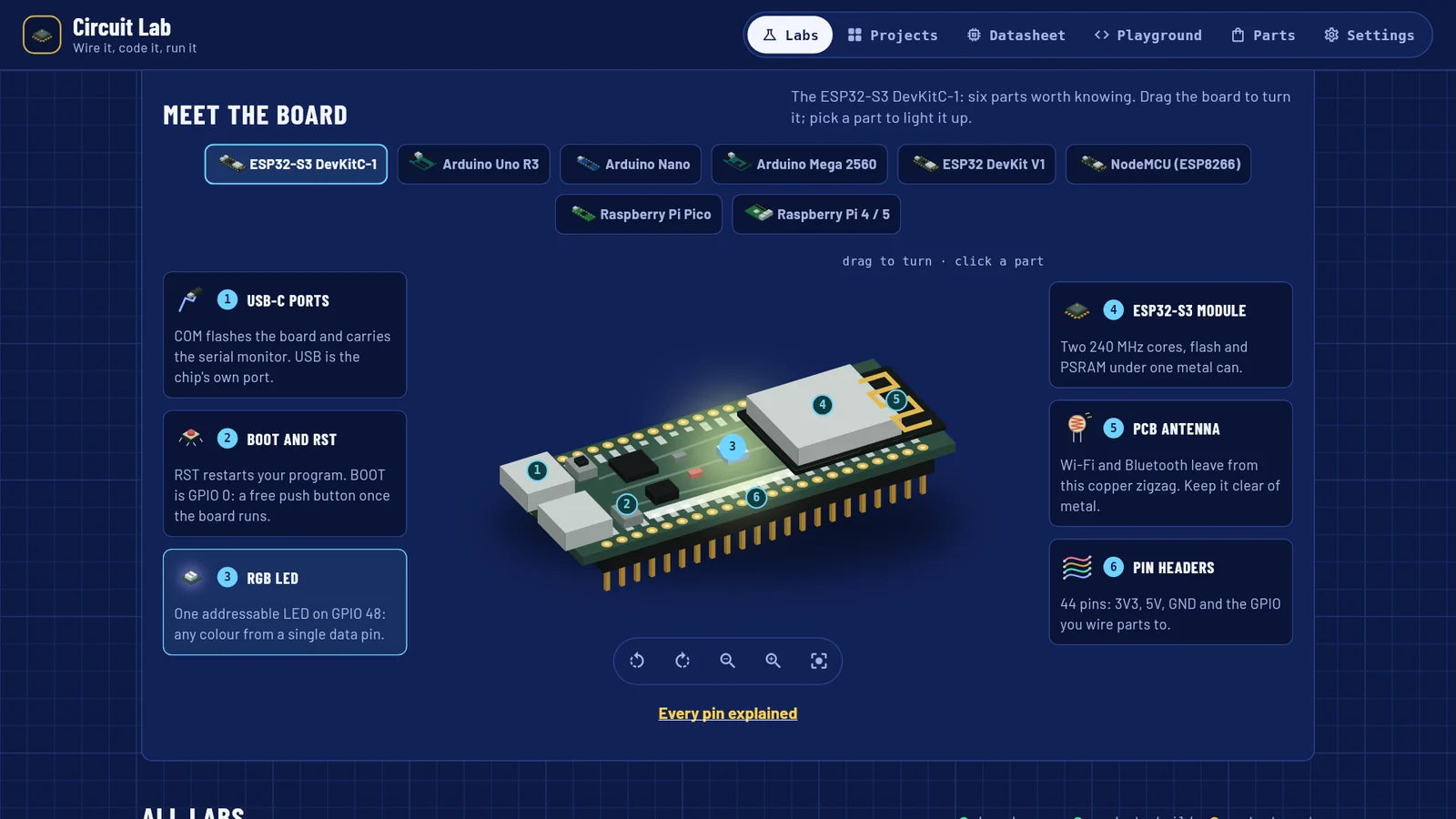
Meet the board, on the Labs tab, shows a 3D model of a board with six numbered parts, each with a card saying what it is for: on the ESP32-S3, for example, its USB-C ports, the BOOT and RST buttons and the RGB LED.
- Drag the board to turn it, or use the buttons under it: Turn left, Turn right, Zoom out, Zoom in and Reset view.
- Select a number on the board, or a card, to light that part up.
- Select another board's name above the model to look at it without changing your board. Make the board my board below the model then switches to it.
- Every pin explained opens the Datasheet tab.
The Datasheet tab
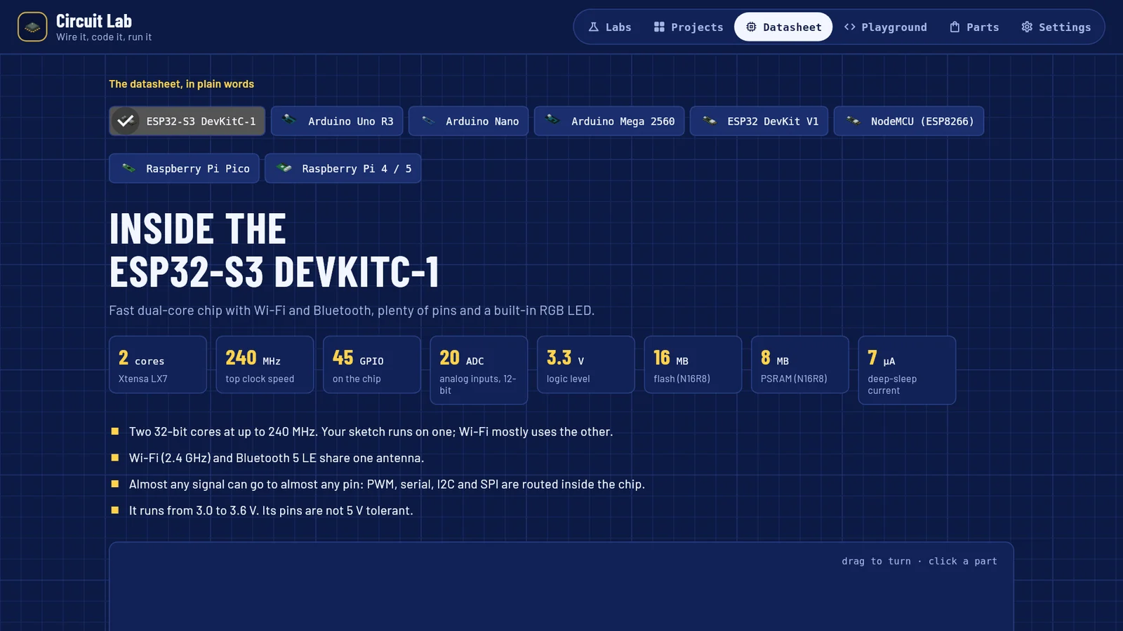
The Datasheet tab describes your board, from the top:
- Inside the board: one sentence about it, tiles with its key figures, such as cores, clock speed, analog inputs, logic voltage and memory, and a few facts in plain words.
- The same 3D model and tour as on the Labs tab.
- Every pin: the board's pin map. Tap a pin to read about it. Each pin is labelled safe pin, avoid unless you know why, power, ground or special, with notes such as whether it can read a voltage, whether it has PWM, and whether it is read at reset.
- Rules that save a board: the few things that damage a board or stop it working, such as which pins to leave free.
- What the simulator covers: what the bench runs, and what only a real board does. See the Reference.
Rules worth knowing
These are the rules the Datasheet tab lists for each board.
| Board | Rules |
|---|---|
| ESP32-S3 DevKitC-1 | GPIO 0, 3, 45 and 46 are read at reset. Prefer GPIO 1 to 10 for analog. Pins 35, 36 and 37 are taken on N16R8 boards. Flash and read the serial monitor through the port marked COM. |
| Arduino Uno R3 | Leave pins 0 and 1 free. Analog readings stop at 1023. Keep each pin under 20 mA. |
| Arduino Nano | Leave D0 and D1 free. A6 and A7 only measure. |
| Arduino Mega 2560 | Leave pins 0 and 1 free. Analog readings stop at 1023. |
| ESP32 DevKit V1 | GPIO 0, 2, 5, 12 and 15 are read at reset. Use GPIO 32 to 39 for analog. GPIO 34 to 39 cannot output. |
| NodeMCU (ESP8266) | D3, D4 and D8 are read at reset. Use D1, D2, D5, D6 and D7 first. |
| Raspberry Pi Pico | 3.3 V only. Three analog pins, GP26 to GP28. |
| Raspberry Pi 4 / 5 | 3.3 V only, and no protection. No analog inputs. Shut down before unplugging. |
WARNING
The datasheets for the ESP32 boards, the Pico and the Raspberry Pi warn that their pins are 3.3 V only: a 5 V signal can destroy the chip. On every 3.3 V board, the designer warns about the common 5 V modules, the HC-SR04 distance sensor and the MQ-2 gas sensor.
The ESP32-S3 pin layout follows the Espressif DevKitC-1 v1.0. Clones are nearly identical, but the labels printed on your own board always win.