
Run a sketch on the bench
Every project opens in the same workspace: a pin map, the guide, the code editor and the bench. This page explains how to run a sketch, work the parts on the breadboard preview, talk to the sketch through the serial monitor, and understand what the simulator tells you.
The workspace
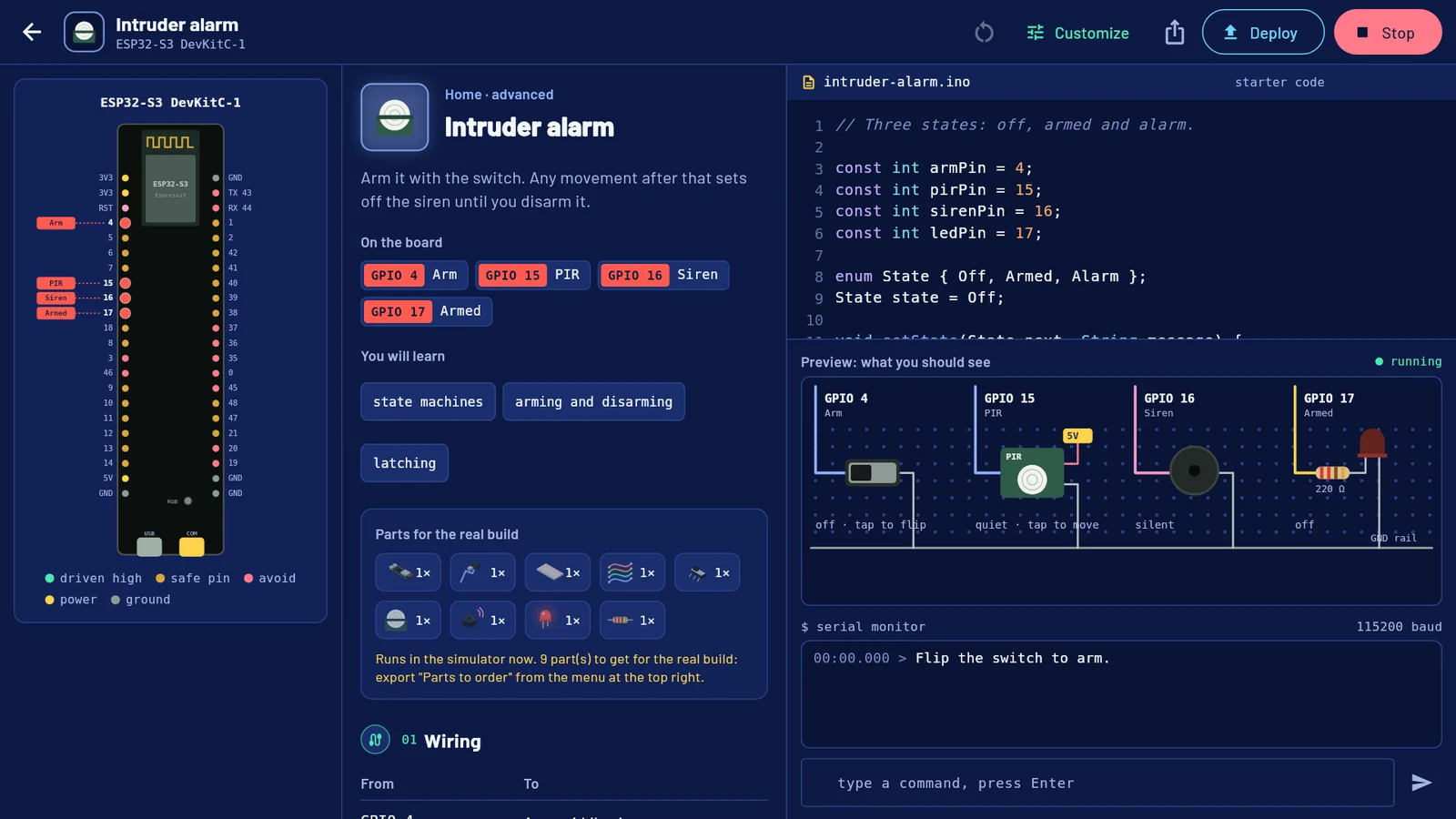
- 1Customize — Makes your own copy, where the circuit can change.
- 2Export — Saves the program, diagram, build sheet, parts list or project file.
- 3Stop — Shows Run while stopped. Ctrl+Enter or F5 does the same.
- 4Guide — What the project does, its parts, the wiring and the steps.
- 5Code editor — The sketch. Your edits are saved as you type.
- 6Pin map — Every pin, with each part tagged on the pin it uses.
- 7Preview — The parts on a breadboard. Press, flip and slide them here.
- 8Serial monitor — What the sketch prints, with the time since it started.
In a wide window the workspace has three columns. In a narrower one, the same parts are tabs: Guide, Code and Bench, plus Circuit in your own projects. The pin map then sits at the top of the Guide tab.
The pin map's colours are explained under it: safe pin, avoid, power and ground. While a sketch runs, pins it drives high are shown as driven high.
Run and stop
Select Run at the top right, or press Ctrl + Enter or F5. The bench shows running, and Run becomes Stop. On a narrow screen the app switches to the Bench tab.
- Each run starts the sketch from the beginning, with an empty serial monitor and the clock at zero.
- What you set on the bench, such as a turned knob or a flipped switch, carries over to the next run.
- The sketch runs in step with real time:
delay(1000)takes a second, andmillis()counts real milliseconds. - A sketch that never pauses does not freeze the app. Select Stop at any time.
A Raspberry Pi 4 / 5 project has no Run button. It shows Runs on the Pi instead, because the app does not simulate a Pi. See Deploy to a real board.
Work the parts
The breadboard preview draws each part with a label under it saying what it is doing. Inputs react to you.
| Part | What you do | What it shows |
|---|---|---|
| LED | Watch | on, off, or the PWM level, such as duty 128/255 |
| Push button, touch sensor | Press and hold | tap and hold; pressed · LOW or touched · HIGH while held |
| Slide switch, tilt switch, door sensor | Tap to flip | Its state and the level the pin reads |
| Motion sensor (PIR), obstacle sensor (IR) | Tap to flip | motion · HIGH or blocked · reads LOW |
| Knob, light, soil, water, gas and sound sensors | Drag the slider | The reading analogRead() returns |
| Temperature sensor | Drag the slider, from −10 to 60 °C | The temperature, starting at 22 °C |
| Distance sensor | Drag the slider, from 2 to 200 cm | The distance, starting at 50 cm |
| Buzzer | Watch | The note's frequency, such as ♪ 440 Hz, or silent |
| Relay | Watch | ON · contact closed or off · contact open |
| Servo | Watch | Its angle in degrees |
| DC motor | Watch | It turns; its speed, running or stopped |
| Laser module | Watch | beam on or off |
The buzzer is drawn, not played: the app makes no sound. The board's own LED is drawn on the board, and the ESP32-S3's RGB LED shows its red, green and blue values.
A soil sensor's slider sets how moist the soil is. Like the real sensor, the reading goes down as the soil gets wetter.
The serial monitor
Everything the sketch prints with Serial.print(), Serial.println() or Serial.printf() appears in the serial monitor. Each line starts with the time since the run began, in minutes, seconds and milliseconds:
00:00.000 > Flip the switch to arm.The monitor keeps the last 500 lines. You can select text in it and copy it. The 115200 baud label is the speed the sketches set with Serial.begin(115200), the speed to use with a real board.
Send a line to the sketch
Type in the box type a command, press Enter and press Enter, or select the send button. Some projects show ready-made commands as buttons above the box; select one to send it. The sketch reads what you send with Serial.available(), Serial.readStringUntil() and similar calls.
Try it with Serial echo, in the Basics group of the Projects tab:
Open Serial echo and select Run. The monitor says
Type something and press Enter.Select the hello button above the box, or type
helloand press Enter.The sketch answers:
textYou said: hello Length: 5 Louder: HELLO
Hints and errors
The simulator watches for mistakes that a real board would make without telling you.
Hints
A hint appears in the serial monitor on a line starting with [sim], in a different colour. The sketch keeps running. Each hint is shown once per run.
| The hint says | What to do |
|---|---|
digitalWrite on a pin does nothing yet | Add pinMode(pin, OUTPUT) in setup() |
| A pin is floating, so it reads at random | Use INPUT_PULLUP in pinMode() |
| A pin is read at reset to pick the boot mode | Move the part to another pin if you can |
A pin has no PWM, so analogWrite only switches it on or off | Use one of the PWM pins the hint lists |
Errors
An error stops the run. It appears in red under the code editor, starting with the line number, and the editor marks that line. For example:
Line 12: 'ledpin' is not declared. Check the spelling, or declare it first.Common errors are a misspelt name, a pin that does not exist on the board, analogRead() on a pin with no analog input, an output on an input-only pin, an array index outside the array, and a function the simulator does not have, such as anything from Wi-Fi or a third-party library. Fix the line and select Run again.
Running in the simulator does not prove the sketch compiles for the real chip. The real compiler is stricter. See What the simulator covers.